Showing posts with label WiFI. Show all posts

Sunday, 18 October 2015

A simple WiFi power cord switch with the OLIMEX ESP8266 evaluation board

Image taken from OLIMEX website

After some months of having a couple of  OLIMEX ESP8266 evaluation boards lying around in my office desk, I decided to jump in the ESP8266 hype train and see by myself how this US$5 WiFi module changed the maker landscape.

I was not dissapointed.

The ESP2866


The ESP8266 is a highly integrated SoC (System on Chip) which includes Xtensa LX106 core processor, RAM, a RF front end and allow WiFi TCP/IP stack to be implemented on board. The ESP8266 is capable of either hosting an application or offloading all WiFi networking functions from another application processor.

I wasn't interested in driving the ESP8266 with another controller, but to flash an application and use it as a stand-alone module, mostly to keep any future BOM as low as possible.  After taking a look at the ESP8266 features it seemed possible to run most applications from within the device:
  • It has GPIO, I2C, ADC, SPI, PWM.
  • A 80 MHz operation frequency
  • 64 Kb of instruction RAM
  • 96 Kb of data RAM
  • 64 Kb boot ROM
  • Winbond W25Q40BVNIG SPI flash
  • RISC architecture
  • The core is a 106micro Diamond Standard core (LX3) made by Tensilica.
As we need to consider also the available resources left for the application taking into the account the stack itself, from this page the actual RAM/ROM are about 40 Kb and 64 Kb.

The ESP8266 evaluation board by OLIMEX features a 220VAC/10A relay module and conveniently exposes most pins in a standard 2.54 mm header, which is great to have available when developing.  It also features an user button which can also be used to put the ESP2866 in bootloader mode, to allow flashing over UART.

Installing the toolchain


The instructions to install the Toolchain were straightforward to use, I had one dependency issue with my current autoconf version, easily fixable with the following:

sudo add-apt-repository ppa:dns/gnu -y

sudo apt-get update -q

sudo apt-get install --only-upgrade autoconf


As a general recommendation install the ESP8266 toolchain as suggested in the /opt/Espressif, as many applications (like the OLIMEX examples and resources) are heavily hard-coded to use this path.

I also recommend to use the suggested Espressif SDK v0.9.3 instead of the newer v.1.2.0, as I (painfully) found that many applications and examples were written for the earlier version, and porting for the new SDK version required more time than I had available for a simple test run.

Flashing the ESP2866


The ESP2866-EVB comes with factory-enabled flash mode, which allows to program the device over UART.  I used a cheap USB to serial converter, wired as shown below.


Image taken from Instructables site


  • GND (blue wire to pin 2)
  • USB to Serial UART RX pin to ESP2866 UART TX (green wire to pin 3)
  • USB to Serial UART TX pin to ESP2866 UART RX (red wire to pin 4)

The ESP8266-EVB datasheet has more information.

To put the device in bootloader mode just make sure the board is powered off, press and hold the user button (the big white one), and while pressing the button power the board (connect to 5VDC).

Making a WiFi enabled power cord switch


I wanted to see how fast would it be to make a connected application.  In nearly 10 minutes I had a WiFi enabled power cord switch.  The motivation was simple: power on and off anything in my house running at 220V/10A from anywhere in the world (as in my bed), without having to cut or adapt any home appliance for this purpose, a non-intrusive approach to keep my wife happy and myself out of the couch.


The specification was simple enough: power the ESP8266 directly from mains and use the relay with the normally open (NO) mode as devices would normally have to be off.  As time was my premise, I destroyed took an USB charger to power up the board, using a multimeter I found the 5VDC/GND pins on the USB charger and solder wires to pins 1 and 2 of the CON3 header.


I kept the USB charger casing to isolate the electronics and avoid someone touching mains by accident.

Now for the firmware I used the stock IoT Firmware image from OLIMEX resources, this handy application allows any web developer to easily control most of the ESP8266 evaluation board features, like managing the wireless network, create and poll events and status related to the user button and relay, manage I2C devices, update the Firmware image remotely, amongst others.
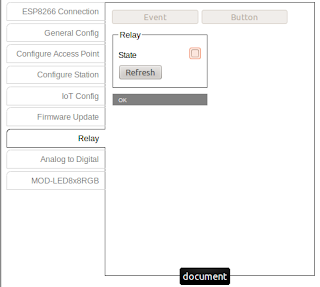
To drive the relay over WiFi the ESP-Sample-Application.html provides a friendly web interface, a screenshot is shown below.

OLIMEX IoT Firmware and sample application

And that's it! a simple WiFi-enabled power cord in 10 minutes.

I tested with a desk lamp and other appliances (under 10A), as it only requires to plug into the female connector of the power cord is easy to use anywhere.

A future enhancement would be to add sensors like an ambient light or temperature sensor, to provide more information about the current location, maybe a presence sensor to allow an event-based operation.  Of course making a proper PCB with a 220VAC/5VDC transformer would be mandatory.

Now to further play with the ESP8266 and dig into the source code.

Thursday, 4 December 2014

Wireless Garden sensing Prototype A and B (Intel Galileo, Spark Core and Grove)

We have a small garden at home and adding sensors to it was merely a matter of time, specially now that winter is coming, and it is time to plant our pepper and tomatoes plants.  Below are the two iterations made to my wireless gardening sensor (still in beta stage).

Prototype A: Intel Galileo on board


For the first prototype I used the Intel Galileo Board I won at Senzations, the objective was to test the sensors, familiarize with the obtained values, and test publishing to Ubidots.  For the test I used my wife's pepper plant.


Light, Temperature and Humidity are variables easy to understand and correlate, but as there was litle information about the Soil Moisture sensor itself, I measured both with the sensor in the free air and submerged into a glass of water, I found out the range was between 0-700 units.  The next step was to water the pepper pot and see the Soil Moisture value when the plant if fully watered, then see the chart going down until the next watering session (when the leaves are "sad" as my wife says), so we can see at which values do we have to trigger an alert.


The actual code was mostly taken from Ubidots examples, as the sensors at this present stage are mostlly analogue, it was only required to use the analogRead() call from the Arduino API.  The sensors are from Grove: the temperature and humidity sensor is I2C-based, the soil moisture and light sensor are analogue.

 Prototype B: Spark Core


With the sensors and the Ubidots platform figured out, the next step was to make the whole thing to run on battery as a stand-alone device.  For this I used the Spark Core I won at IoTogether Hackaton along with a battery charger board I steal borrowed from work, and a 3.7V 800mAh Li-ion battery connected to a battery charging circuit.

To avoid having to solder a wire to the USB 5VDC pin I added a scrambled jumper logic to enable charging the battery when connected to the micro-USB, else the Spark Core will be powered by the battery only.  I have also one power input to throw in a solar panel and charge the battery in the day and discharge over the night, but I still have to figure out how to adapt it to the enclosure.


I added 2 Phidget-like connector to be able to connect Phidget sensors or analog ones following the same pin-out (VDC/GND/Signal), and one Ziglet-like connector to connect any I2C-based sensor, as at the end I want to use digital sensors to keep the power consumption as low as possible, having wired a GPIO pin also to the connector to use interrupts from the sensors as well.

The male pin-header exposes unused GPIOs to be used later, for example one wandering idea is to add an MP3 board with an amplifier and a small speaker, as allegedly this helps plants grow, or maybe do a playback of my wife talking to the plants, which one was it? nevertheless it would also be kinda cool to play nature music when presence is detected... this will be likely an improvement to make if the power consumption can be kept low.

One caveat: I was one of the unlucky Spark owners who had a board with faulty DNS resolve, so I had to include an external DNS client to resolve Ubidots IP address, and then add the host property to my header and initiliaze the Server IP address as shown below:
http_header_t headers[] = {
     { "Content-Type", "application/json" },
     { "X-Auth-Token" , TOKEN },
     { "host", "things.ubidots.com" },
     { NULL, NULL }
};

IPAddress dnsServerIP(8,8,8,8);
IPAddress remote_addr;
DNSClient dns;

char serverName[] = "things.ubidots.com";

void setup() {
    request.port = 80;    
    dns.begin(dnsServerIP);
    dns.getHostByName(serverName, remote_addr);
    request.ip = remote_addr;
}

Then to take advantage of the Spark low power mode and try to save battery as most as possible, I use the SLEEP_DEEP_MODE to put the Spark to sleep and awake after 5 minutes, rebooting the code with no memory retention, which is fine in my case as I only want to take single readings and upstream these.  The code runs as follows:

void loop() {
    
    // Read data from the sensors
    getData();
    
    // Send data to Ubidots
    postData();
    
    // Short blink to indicate we have finished posted
    blink_led(500);

    // Stay awake enough time to allow being reprogramed        
    delay(AWAKE_BEFORE_SLEEP);
        
    // Put the core back to sleep
    Spark.sleep(SLEEP_MODE_DEEP, SLEEP_SECONDS);
}

The AWAKE_BEFORE_SLEEP delay makes sure the Spark Core stays awake for 20 seconds, which gives me enough time to reprogram the Spark over the Web IDE from my PC without having to connect the Spark to the host over USB.  One of the things on my to-do list is to measure the current consumption of the device.

The whole thing fits into a standard enclosure, one of the things I have still pending to do is to adapt the sensors to the enclosure, make a small window to be able to visualize the LED, and also fix the solar panel.  I have convinced my daughters to paint the enclosure with a festive theme, so surely I will post this anytime soon.


So that's it, I'm hoping in the holidays to have time to improve the Prototype B, make some measurements and work on the solar panel.  One of the things I will surely test is the ESP8266 cheap WiFI board, but with my Photon already ordered in pre-sale for next year, I think it will make worth the wait, in time for the Prototype C, maybe even a release.


Wednesday, 23 July 2014

Quick note: Raspberry Pi WiFI client configuration (tested with ralink RT5370)

I recently purchased a WiFi dongle as the new addition for my Raspberry Pi, this cheap and amazing piece of work from ebay is a 150M USB WiFi Wireless Adapter LAN, with a 2dBi de-attachable Antenna and the well-known ralink rt5370 Chip, for only 3€ (at the purchase time) what else could you ask for?


OK, it took a while to arrive to Spain as it was sent from China, but the product was worth the wait!


Not only worked flawlessly with the Raspberry Pi (mine is mounted on the wall next to my desk, sometimes I put it behind my monitor as the enclosure is VESA-compatible, see previous post), but also worked out-of-the-box for my LG 47LA640S Smart TV, saving me from having to buy an "official" overpriced WiFI USB dongle (30€, 6 times the value!) or adding yet-another wireless router to connect my TV over ethernet.

To enable the Raspberry Pi to connect to an AP with a static IP address, just add this to your /etc/network/interface file:

allow-hotplug wlan0

auto wlan0


iface wlan0 inet static
address 192.168.1.232
netmask 255.255.255.0
gateway 192.168.1.1

dns-nameserver 8.8.8.8


wpa-ssid "SSID-example-replace-yours-here"

wpa-psk "replace-your-WPA-password"

This will work as long as your AP has WPA/WPA2 security and is not hidden.