Showing posts with label IoT. Show all posts

Sunday, 18 October 2015

A simple WiFi power cord switch with the OLIMEX ESP8266 evaluation board

Image taken from OLIMEX website

After some months of having a couple of  OLIMEX ESP8266 evaluation boards lying around in my office desk, I decided to jump in the ESP8266 hype train and see by myself how this US$5 WiFi module changed the maker landscape.

I was not dissapointed.

The ESP2866


The ESP8266 is a highly integrated SoC (System on Chip) which includes Xtensa LX106 core processor, RAM, a RF front end and allow WiFi TCP/IP stack to be implemented on board. The ESP8266 is capable of either hosting an application or offloading all WiFi networking functions from another application processor.

I wasn't interested in driving the ESP8266 with another controller, but to flash an application and use it as a stand-alone module, mostly to keep any future BOM as low as possible.  After taking a look at the ESP8266 features it seemed possible to run most applications from within the device:
  • It has GPIO, I2C, ADC, SPI, PWM.
  • A 80 MHz operation frequency
  • 64 Kb of instruction RAM
  • 96 Kb of data RAM
  • 64 Kb boot ROM
  • Winbond W25Q40BVNIG SPI flash
  • RISC architecture
  • The core is a 106micro Diamond Standard core (LX3) made by Tensilica.
As we need to consider also the available resources left for the application taking into the account the stack itself, from this page the actual RAM/ROM are about 40 Kb and 64 Kb.

The ESP8266 evaluation board by OLIMEX features a 220VAC/10A relay module and conveniently exposes most pins in a standard 2.54 mm header, which is great to have available when developing.  It also features an user button which can also be used to put the ESP2866 in bootloader mode, to allow flashing over UART.

Installing the toolchain


The instructions to install the Toolchain were straightforward to use, I had one dependency issue with my current autoconf version, easily fixable with the following:

sudo add-apt-repository ppa:dns/gnu -y

sudo apt-get update -q

sudo apt-get install --only-upgrade autoconf


As a general recommendation install the ESP8266 toolchain as suggested in the /opt/Espressif, as many applications (like the OLIMEX examples and resources) are heavily hard-coded to use this path.

I also recommend to use the suggested Espressif SDK v0.9.3 instead of the newer v.1.2.0, as I (painfully) found that many applications and examples were written for the earlier version, and porting for the new SDK version required more time than I had available for a simple test run.

Flashing the ESP2866


The ESP2866-EVB comes with factory-enabled flash mode, which allows to program the device over UART.  I used a cheap USB to serial converter, wired as shown below.


Image taken from Instructables site


  • GND (blue wire to pin 2)
  • USB to Serial UART RX pin to ESP2866 UART TX (green wire to pin 3)
  • USB to Serial UART TX pin to ESP2866 UART RX (red wire to pin 4)

The ESP8266-EVB datasheet has more information.

To put the device in bootloader mode just make sure the board is powered off, press and hold the user button (the big white one), and while pressing the button power the board (connect to 5VDC).

Making a WiFi enabled power cord switch


I wanted to see how fast would it be to make a connected application.  In nearly 10 minutes I had a WiFi enabled power cord switch.  The motivation was simple: power on and off anything in my house running at 220V/10A from anywhere in the world (as in my bed), without having to cut or adapt any home appliance for this purpose, a non-intrusive approach to keep my wife happy and myself out of the couch.


The specification was simple enough: power the ESP8266 directly from mains and use the relay with the normally open (NO) mode as devices would normally have to be off.  As time was my premise, I destroyed took an USB charger to power up the board, using a multimeter I found the 5VDC/GND pins on the USB charger and solder wires to pins 1 and 2 of the CON3 header.


I kept the USB charger casing to isolate the electronics and avoid someone touching mains by accident.

Now for the firmware I used the stock IoT Firmware image from OLIMEX resources, this handy application allows any web developer to easily control most of the ESP8266 evaluation board features, like managing the wireless network, create and poll events and status related to the user button and relay, manage I2C devices, update the Firmware image remotely, amongst others.
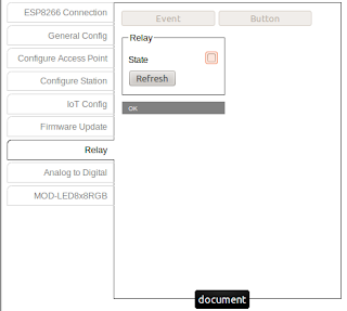
To drive the relay over WiFi the ESP-Sample-Application.html provides a friendly web interface, a screenshot is shown below.

OLIMEX IoT Firmware and sample application

And that's it! a simple WiFi-enabled power cord in 10 minutes.

I tested with a desk lamp and other appliances (under 10A), as it only requires to plug into the female connector of the power cord is easy to use anywhere.

A future enhancement would be to add sensors like an ambient light or temperature sensor, to provide more information about the current location, maybe a presence sensor to allow an event-based operation.  Of course making a proper PCB with a 220VAC/5VDC transformer would be mandatory.

Now to further play with the ESP8266 and dig into the source code.

Tuesday, 2 December 2014

Disable 6lbr to be launched at boot


I luckily found out 6lbr some months ago (I have an unfinished post about it yet to finish, loving foren6 also), but I needed to stop the service to be launched from boot while I did some testing.  As I didn't found any configuration tweak to do so, I disabled the service at all /etc/rcX.d run levels using the well known update-rc.d script.

update-rc.d -f 6lbr remove

To enable back:

update-rc.d 6lbr defaults

And business as usual.

Sunday, 30 November 2014

IoTogether Hackaton 2014: IoT loving with the LoveTotem


 IoTogether was a competition event for 7-8 co-located teams in Trento and Barcelona. Remote teams will be composed by participants from both sides who will be asked to interact via Future Internet videoconferencing tool provided by the SPECIFI project.

Sponsors: SPECIFI, COMPOSE and VISIONAIR.
Partnership: CREATE-NET, MuSe, BCNLab, I2CAT and the City of Barcelona.
***

The idea was as freaky as it could get, is a lot funnier to start explaining our team concept from the prototyping stage up to the final application...

At the Barcelona location we implemented a force sensor with a 3-axis accelerometer integrated to a wool glove, to measure both force of impact, movement and acceleration, displayer over a LED bar for our viewing pleasure, hooked up with a GSR (Galvanic Skin Response) sensor to measure the "arousal" level of its wearer.  To interface the sensors we used an Arduino bundled with a WiFI module, to send the sensed data over Glue.Things to the Trento location.

We did also manage to send data to Ubidots and The Things.IO.


At Trento side there was a dildo-shaped lamp (yes, a dildo), changing colors according to the data received from the glove by selectively turning RGB LEDs, using force, acceleration, arousal and muscular response data... well, you know, leave it to the Italians to sex-it up a Hackaton :)

One of the main challenge of the event was actually to set up everything from each side while talking to each group, unfortunately the co-location resources went bad and we ended up talking over Skype, and emulating both input and outputs isolated, but at the end we were glad it worked out.


The official name of the project was "The LoveTotem", to be honest the horny lamp would be a better name, but regardeless the name of the actual use case, what was interesting about the project, and the event, was to put a bunch of people together, with the right tools and attitude, and create something, whatever, as long as it works, you cannot save the world with a killer app in 4 hours, but building "anything" is the first step to get more stuff rolling... who knows? everything can be reused and interpreted in many different ways, with a different angle this would also make a good physical rehabilitation tool, a social game to take introverts into social engaging with physycal interaction with others, nnevertheless, I loved the lamp challenge... it was so out of my field that it was cool to try to design a matching application to feed love to the Totem.

 This was the official description of the project:
"LoveTotem": Suppose you are too far from your sweetheart and you want to know how really he/she feels, or share emotions without talk! Your partner can wear the LoveSensors: when you'll turn on your LoveTotem, you'll see it take strong/hot color if your partner is excited, or soft blue light if is relaxed. Love Totem uses an open hardware platform (Arduno Yun) and human sensors like (Muscle sensor,Temperature/Humidity, GSR) in order to track the state of a person and transmits these data through dedicated API to a cloud platform (GlueThings). On the other side, another Love Totem will retrieve these data, representing them with a mix of some colored leds. Leds are placed in a lamp, which we have designed and made using a laser cutter and a 3d printer.
At the end our team was one of the two winning teams of the event, with a caveat: the team members posted at SPECIFI site is wrong, Barcelona's team members are swapped with other team (Aitor is actually a colleague of work, but at a different group), the correct line-up is the following: Andrés Hernández Casaus, Hector Esteller, Pablo Carbajal and yours truly.

We got plenty of goodies, including Spark Cores for each of the members, sensors (I got a soil moisture sensor, the GSR and a couple of buzzers), along with a Shield-Shield.

Here is the full list of the developed projects:
  1. "SeeTy": a urban garden community that merges gardens around the world.
  2. "LoveTotem": a lamp to express remote feelings for lovers.
  3. "WineCheck": check wine bottles temperatures on your smartphone.
  4. "Remote Interactive House Control": remote management of houses temperature & humidity.
  5. "EmotionalBag": a bag monitoring and displaying its user's emotional status.
  6. "SmartGlove": a glove that senses the heart beat and the level of stress.
  7. "BluePresence": a smartwatch managing smartlights with power consumption profiling.
  8. "CarFinder": cars tracking on the web with GPS sensor.
If you ever stumble upon a Hackaton organized by the same people behind IoTogether, be sure to attend, besides the good folks assisting the event, and the electronic goodies, the food was sincerely amazing, no cold pizzas and warm beers, a full-catered event with food coming and going at the pace of cold beer and hot coffee, just what a maker needs.

Saturday, 29 November 2014

Senzations 2014 IoT school and City Karma


I recently was lucky enough to attend Technical track of Senzations 2014 Summer School hosted in Biograd na Moru, Croatia.  It was an incredible experience traveling to Croatia, without taking merits to the event itself, one of the things I enjoyed the most was the City experience, and of course the Boat trip to the National Park Kornati.

The lecturers were great and gave plenty of insights on both Wireless Sensor Networks, M2M and IoT,and shared their current work on the field, most of the slides are available at the Program website, but I though about sharing some of the presentation links below:


As Intel was supporting the event, there were plenty of Intel Galileo development kits to use to prototype our very own IoT-driven applications, the core of the event: divide into teams and create an IoT application from the prototype to the business plan.  Here's mine with plenty of Grove sensors from SeeedStudio attached in the prototype phase.


Our team, the DreamTeam, scored big time and was one of the winners of the 4-days Hackaton with our project: City Karma, which had its own dorky video as well! The main idea was to target the lack of social awareness in cities, and City Karma was born:

A big shout to the DreamTeam: Berta Jadro, Adela Sockovic, Bruno Dunaj, Nikola Paic, Ivan Jokic, Stevan Jokic


The application was implemented using a Python script running in the Galileo Board, monitoring 3 types of events: loud scream for help, emergency button and assistance button, then posting a Twitter message indicating the location of the event, type and date, with a randomly generated Karma Code.  A person following the #CityKarma hashtag or the CityKarma twitter account then could see the new event, and could reply the Twitter message to inform the person in distress that help its on its way.

A mobile application would also allow to flash this alert to the screen, by monitoring the City Karma feed and using the user location to see if the user is nearby.


Then the helping hand would get Karma Points, plenty useful to show off and maybe get a free expresso or a discount in affiliated partners, maybe a nice tax reduction? what would it take for you to go out of your way and help a stranger?  Could you ignore a person nearby you asking for help? Let's hope the people frequenting this blog are natural Karma sponges, if not remember this:
When you carry out acts of kindness you get a wonderful feeling inside. It is as though something inside your body responds and says, yes, this is how I ought to feel. - Harold Kushner
The application was powered by MQTT over WiFI/GPRS, using a local Node-RED server to receive the help message, parse and post it to Twitter, and also to track the Twitter feed for responses, posting an update on the MQTT topic to notify the person in distress that his help request has been answered, by means of a LED notification.


If you want to take a peep at the code it is uploaded in my Github, keep in mind this is not production-ready code and was done only as a proof-of-concept.

To wrap this up, I'm really looking forward to next year event, I hope I can assist as both a participant or a lecturer, it was an incredible gathering of talent and knowledge, and a fun crowd to hang out.  A big thanks to Srdjan Krco (DunavNET) for organizing the event, Alex Gluhak (Intel Labs) for rolling out the hackaton and providing the equipment and tech support, and Charalampos Doukas/Jan Pernecky for the memories.


The presentation videos are available at Senzations YouTube channel

Monday, 12 May 2014

Using Telecom Design's TD120x as a SIGFOX gateway with a Z1 mote


As mentioned in an earlier post, I recently got a demo kit from SIGFOX and finally I had some time to start playing with.

I had a head start and told that the starter kit was based on Telecom Design TD1204, which provides a serial AT-based modem to allow communication over a serial link, so it made easier testing using software tools like PuTTY, Hercules and then moving to a Zolertia Z1 mote to drive the TD1204 over its serial port (at the end of the post!).

Note: You need to have a device registered in the TelecomDesign cloud or the SigFox backend for some of the following steps, but nevertheless is is interesting to watch and to take a peep inside.


SIGFOX Back-end


I started by browsing the web-based SIGFOX backend, by clicking on the Device tab (as shown below) we can see the devices associated to our account, my starter kit device appears listed there.


I work in Barcelona, so I was interested in checking if my workplace is under SIGFOX coverage area, so by clicking the Location tab at the left it is shown an approximate coverage map.  (btw, I have tried pushing a message while at home in Cerdanyola del Vallès, but it didn't reach the network, but generally in Barcelona the coverage is OK).  At first glance it made more sense to me to represent the light blue area as a circle rather than using a square, but as I'm not sure of how this is modeled, it is fine as it is at the moment.


 Then the moment of truth, let's see what happens when I long-press-and-hold the button... once or twice to be sure, the message board is updated showing the content of the test message... I don't understand what the data means (180c62, 190c62), but I have a good idea about the rest of the fields...


  • Delay: Time (in seconds) elapsed since the message was triggered and then received by the network station.
  • TAP: Station receiving the message, as these stations are fairly identified you can get the estimated location of your device (a way estimated location).
  • RSSI: Received Strength Signal Indication: as shown we have values ranging from -124/-128dBm, as it was already discussed in my previous post, the sensitivity value is expected to be quite low, as the wireless range is favored by the low data rate and bandwidth.  In the  TD1204 EB page the sensitivity value is stated to be close to -126dBm, as we are using a 5dBi external antenna we can expect a boost (in one occasion I got a RSSI value of -132dBm, so this approximation seems to be OK).
  • Signal (dB)
  • Freq (MHz): channel used in the transmission, as shown above the channel is changed for every retransmission attempt.
  • Rep: Numbers of retransmission attempts needed for the packet to actually arrive to the network.
  • Callbacks: Event triggered upon receiving the packet, below is an example of the callback generated by the user-button event (an email is sent every time to a given email address):
          [OK] - TAP 0146 - 1 second
     200 -
     {device} (name@mail.com)

The maximum transmission power of the radio transceiver is 14dBm (for the TD1204 DK), but it would be interesting to check if SIGFOX allows devices to be on the ETSI G3 sub-band (869.4-869.65 MHz 500mW), one thing pending to confirm (in my previous post I assumed so).


Hands-on: connecting SIGFOX to a Z1 mote 


So OK, enough of using the user button and the backend (we will return to this later when setting callbacks and stuff), now let's move to the meaty part of the testing: sending a custom string message.  After checking the TD 1204 reference manual, I found the required serial settings to connect the starter kit to the PC:
  • Speed 9600 bps.
  • 8 data bits.
  • 1 stop bit.
  • No parity, no hardware/software flow control.
I first tested the serial communication using Hercules and the result was OK as expected (remember to add a carriage return at the end of the string, more information about the command/response expected format is found in the TD1204 reference manual, section 2.4).

.

After verifying the serial communication then I moved to wiring the starter kit to the Z1 mote.

At first It seemed a good idea to cut-off the male USB connector of an USB male to mini-USB cable, strip the wires and solder those to the Z1 mote, wiring D+/D- to the UART1's RX/TX (P3.7/P3.6), and power the starter kit by soldering GND/VCC to the Z1's USBGND/USB+5V (requiring to power the Z1 through its micro-USB port)... but this was a rather bad idea, as I noticed when connecting the TD1204 to the PC that it uses a FTDI chip, which are normally slaves thus requiring a master to communicate.  The Z1 mote has a CP210x serial-to-USB converter too, but my original intention was to use raw serial communication using a free UART port of the Z1 mote, so its USB port (wired to UART0) can be kept as a programming/debugging port, avoiding to use the JTAG port instead.


So the next logical step (off course, without a doubt) was to void the warranty and take a peek inside the demo kit... I love voiding warranties :-)

Finding the FTDI reference (FT232R-L package) chip was easy, as suspected there's a battery charger/Modem enabling circuit, a 1000mAh LiPo battery and the user button on one side, on the other we can see a TD1202 radio transceiver and AT-modem (sending an AT&V command is also a good way to find out about board-specifics).


Next I needed to locate the serial RX/TX lines going to the TD1202 transceiver to bypass the FTDI, following the FTDI pin-out and the PCB trace I noticed there were 2 0Ohm resistors standing between the FTDI and the modem, a nice gesture as it only required to apply a little heat and lift-up the resistors instead of cutting the PCB.  

The location of the RX (red), TX (white) and GND (black) pads are shown above, as well as the location of the resistors.  We cross-wired the Z1 and TD1202 RX/TX lines, and the DGND pin of the Z1 to GND.


I could also directly power the TD1202 using the Z1's 3.3V power reference, but honestly I was more interested in testing the communication between the Z1 and the board, than worrying about how to power the device, so I kept using the mini-USB port to power up the TD1202 through the 5V delivered by the Z1 connected via USB as shown below... a work to be done later is to replace the LiPo battery with one that has a larger capacity, and hook it up to a solar panel, but that's material for another post.


I used a logic analyser to verify the communication between the Z1 and the TD1202 was OK, and programmed the Z1 mote using TinyOS with a simple serial test sending an AT\n command every second, hoping to receive the AT command echoed back and an OK from the AT-modem, the result is shown below.


Here's the snippet of code used for the test.  The TMP102 temperature sensor callback event is shown on purpose, it will be used later to forward temperature readings from the mote.


Maybe someday I'll write a driver in Contiki/TinyOS to allow a more flexible and API-like way to communicate with the TD120x, or just port my sub-1GHz based mote to native support SIGFOX, but for preliminary testing sending raw strings is acceptable.

As the serial communication is asserted I can dump now the logic analyser and just print out the responses from the TD120x to console by modifying the code, adding a first print after boot to check out device information such as version.


Z1 with a SIGFOX interface


After checking the TD120x documentation the command to send data is quite straightforward:
AT$SS=[HEX1][HEX2]... [HEX12]

As mentioned before, up to 12 bytes can be sent in any transaction, more than enough for sending a 16-bit temperature reading from the Z1's built-in TMP temperature sensor.

The sending command expects a number of even hexadecimal "symbols" to be sent, meaning if you have 0x123 the modem will return an error, as it expects something like 0x0123.  All data should be sent encoded as hexadecimal, and leading zeroes might be needed depending on your data format.

After wiring my temperature sensor callbacks to be forwarded to SIGFOX the following messages were received, showing the mote was close to 28.5ºC at the moment of the test.  Most of my messages are being sent close to the 868Mhz frequency, maybe SIGFOX operates solely on the G1 sub-band?


The code used for testing is available at Github.

Wrapping up...


If you like to outgrown the demo, you could add more motes and add radio communication, and use the TD120x-enabled mote as a Gateway with dual wireless interface: sub-1GHz and 2.4Ghz, allowing to forward messages to SIGFOX while locally using other network topologies and protocols, not limited by SIGFOX packet size/throughput, only pushing important data and events such as alarms, periodic readings and others.

So this is the end of the post, I still need to test the callbacks and customising the TD120x using the SDK ,but this post has grown too much already, so I'll leave more for later.


Thursday, 1 May 2014

Unboxing and testing the Thingsquare IoT kit


Some months ago the Thingsquare folks hosted a contest to help spreading the world abouth Thingsquare and their wireless mesh networking and connectivity solution to the Internet of Things (see chached details about the contest here)... well, luckily I was one of the winners of the The Thingsquare IoT Kit (a limited edition unavailable now), featuring:
  • USB cables.
  • Ethernet cable.
  • SmartRF06 evaluation boards, featuring a LCD, buttons and plenty of test points, with on-board accelerometer, light sensor and UART back-channel over USB.
  • Radio System on a Chip (SoC) boards(TI CC2538-based), featuring an ARM Cortex M3-based MCU system with 32K RAM, 512 KB flash,  alongside a 2.4GHz radio transceiver, IEEE 802.15.4 compatible.
  • An Olimex MOD-ENC28J60-based Ethernet connectivity router.
  • Login credentials for the Thingsquare server.
  • Cool stickers!. 
Running on top of Contiki operative system of course.

Here it is after unboxing:

Thingsquare's IoT kit unboxed

The setup was quite straight-forward: 

Just assemble the Router-labeled node together, bundling the ethernet board onto the intermediate assembly board, on top of the SmartRF06 board (quite a sandwich there), and plug-in the CC2538EM with the router label.  Once the router was assembled I only had to connect it to one of my router's free LAN port through the provided ethernet cable, power the evaluation board through the uUSB port (be sure to enable powering via USB by moving the SOURCE switch to USB, and to place the jumper to connect VDD and EB power pins on the SoC board). 

After powering the board, a green LED next to the ethernet board should lit up and the yellow one will start blinking, another green LED on the board will start blinking until obtaining an IPv4 address from the router, the it will stop blinking... I did not catch this at first (an engineers motto taken from Tropic Thunder: we don't read manuals, manuals read us!), I was expecting "something" to show up on the LED display but no feedback there (I was tempted to replace the board's display to discard a broken unit), but as I was already on my routers box management utility, I found the assigned IP address given by the DHCP server, and test connectivity to the board with an extended ping.

To assemble the remaining nodes just plug in the SoC boards on top of the SmartRF06 boards, and power as above.  

A quick photo of both nodes back-to-back is show below:

Router and device back-to-back

The nodes will display the follow progress messages over the LCD display:
Waiting for wireless network
Waiting for Internet DNS
Waiting for server connection
Register PIN ##### at thingsquare.com
 If everything goes well then you should get a PIN number for each node (except the Router).

Registering the device is quite simple, at the Thingsquare's demo page just register the device and name it, the node's LED display will be updated quickly afterwards, in case you are wondering mine's Luffy (you can expect the rest of the tripulation to jump in anytime):

The node registered and ready

The demo has some cool stuff, what I liked the most was to actual develop code on the web browser and then remotely compile and flash the node, allowing to pause/continue the device after being programmed, and commanding the device to blink on request to assert it is running, simple but always useful, specially when introducing people to the IoT world and needing to show some real hardware doing wireless "stuff" (do not under appreciate the commercial power of a blinking LED!). 

Thingsquare browser-based IDE


The setup was simply enough to have it ready in 5 minutes, the demo page is very straight-forward to follow and the code examples and shown features briefly show the capabilities and possibilities of  the system, below are some cool examples of a sensor metering system and an intelligent street lighting deployment.


The development kit is quite complete and it was a great addition to my collection: TI evaluation boards are well suited for testing, prototyping and the TI CC2538 support on Contiki is coming along just great, and as Thingsquare actively contributes to Contiki (heck, the CEO is Adam Dunkels), one can expect nodes and products based on this SoC to be a popular choice amongst developers.

I will continue testing, I missed to take some wireshark pcap screenshots, so hopefully I will update this anytime soon.

Wednesday, 23 April 2014

Discovering Sigfox

Image taken from www.sigfox.com
A few weeks ago We were invited to a workshop hosted by Abertis Spain, introducing SIGFOX: a cellular/mobile provider offering no less than connectivity for the Internet of Things through its star-based cell infrastructure, acting as a transport channel, even for devices running on batteries.

In a telecommunication market vastly competing for higher bandwidth and high data rates, SIGFOX proposal is quite simple yet appealing: lower data rates and low power consumption equals lower rates/prices (€1-€14), which is good as you can plan ahead what billing plan fits your expected data traffic, giving you exact numbers when having to dimension your network and its possible growth.

Abertis Telecom is SIGFOX operator in Spain, allowing to use its telecommunications infrastructure (broadcast, satellite and mobile communications) to support applications built on top of SIGFOX.  This is a good thing to have in mind when planning a network and its possible growth over time, specially in Smart Citiy applications in which new devices have to be added to either expand the service coverage or add new features, to zones that may lack the proper infrastructure, thus avoiding extra civil work.

But of course, coverage can still be a problem for any RF-based solution :)

As most IoT/WSN applications at the end can be simplified to a basic origin/sink approach, the SIGFOX model can be embraced and ported to existing applications, keeping the power consumption as low as the transceiver allows, as taken from the SIGFOX page:

"Typical emission consumption of a SIGFOX Ready™ modem varies from 20mA to 70mA and they consume next to nothing when inactive"
Which is possible of course by restricting data traffic to one-direction only with low updating rates :)

Now the technical part:

What I found atractive about SIGFOX was the fact that they use sub 1-GHz RF transceivers, thus anyone can port its existing application and adapt to its protocol, not having to purchase a specific radio model or closed HW, as SIGFOX bussiness is focused only on being the carrier, however a certification process is required as expected.

SIGFOX operates in ISM bands (license-free frequency bands), it currently uses 868MHz on Europe (as defined by ETSI and CEPT) and the 902MHz in the USA (as regulated by the FCC), offering different profiles or classes, 0-3, being 3 the worst, mostly for well-covered zones.  I imagine the difference between classes is the transmission power levels, which is expected as to avoid self-interference the wisest thing to do is to confine devices into its cell, avoiding overhearing and interfering with each other and others.

As said earlier, SIGFOX focuses on low throughput devices, restricted to send up to 140 messages per day, each message of maximum 12 bytes (payload data).  Altough this may seem as too low compared to most byte-hungry messages going on the airwaves (up to 128 bytes for most RF transceivers), it actually fits most existing applications, leaving just enough space for data and sensor readings (up to six sensors each with 16-bits measures).  The slow data rate is expected (RSSI are close to -130dBm, so I'm guessing >1Kbps), and in fact is what SIGFOX is promoting, so you will need to think your application towards these constrains, fortunately there are quite a few possible scenarios in which this will work.

My main concern is of course self-interference, as it is right now with fewer radio stations installed all around, reaching to an existing one may require transmitting at a higher power, which in CEPT region places us below the 500mW limit of the 869.400-869.650MHz band, where you can have channels up to 25KHz or even use the whole bandwidth as a high-velocity channel.  The AFA/LBT/duty cycle requirements of the regulation mitigates to some point the self-interference, SIGFOX devices do not use a fixed frequency channel but a random one so there is lesser chances to being interfered twice, also as update rates are quite low, retransmissions attempts can be sky-rocketed as no close to real-time responses are expected, but not all applications are as relaxed.  As we already know, with proper network planning and infrastructure deployment, cells can be adjusted and dimensioned to restrict this effect and the class concept plays an important role in this, but this is a known and expected problem needed to be addressed eventually (surely it is already on their mind!).

The folks at Abertis were kind enough to give free SIGFOX demonstrators, here's ours:

SIGFOX demonstrator with short antenna and user button (back)

The next step will be testing the kit myself and try to sniff some traffic, adapt my sub-1GHz node (a CC1120-based device running on top of a TI MCU) to SIGFOX and develop a simple demo, some colleagues at the office have interesting ideas about what to connect to.

 Documentation available Here